AVR basic programming tutorial: In the following AVR microcontrollers tutorial i used books to learn fundamental knowledge about Embedded system. Microcontrollers will often allow an optimal solution,combining complex functionality with reduced part count.ATMEL AVR chips pack lots of power (1MIPS/MHz, clocks up to 16MHz) and space (upto 128K of flash program memory and 4K of EEPROM and SRAM) at low prices.
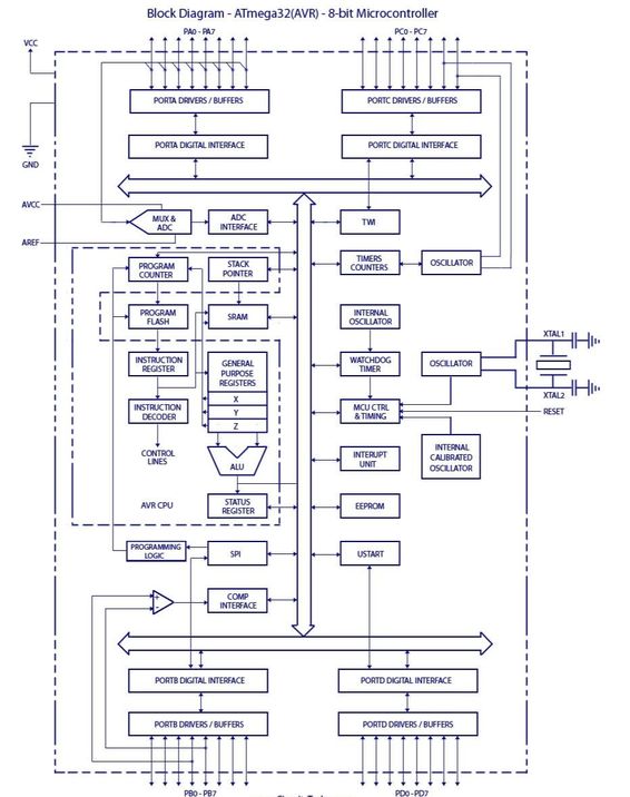
ATMEGA32(AVR) Introduction: ATmega32 is belongs toAtmel’s AVR series micro controller family. CMOS RISC, AVR ATmega32 8-BIT Microcontroller, In-system Programmable with Flash code storage, re-programmble up to 1000 times. Features 32 working registers, single clock cycle execution giving up to 1MIPs/MHz.
KEY FEATURES OF ATmega32 (AVR) ARCHITECTURE:
32Kbytes Flash Program Memory
2Kbyte Internal SRAM
1024 Bytes EEPROM
2 x 8-Bit Timer/Counters and 1 x 16-Bit
Timer/Counter
Four PWM Channels
8 Channel 10-Bit ADC
Programmable Serial USART
Master / Slave SPI Interface
Programmable Watchdog Timer
32 Programmable I/O Lines
On-chip Analog Comparator
Six Sleep Modes for Current Consumption Minimization
Programmable Lock for Program Security
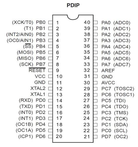
Pin configuration:
PIN DESCRIPTION: VCC-Digital supply voltage. GND-Ground. Port A (PA7..PA0)-Port A serves as the analog inputs to the A/D Converter. Port A also serves as an 8-bit bi-directional I/O port, if the A/D Converter is not used. Port pins can provide internal pull-up resistors (selected for each bit). The Port A output buffers have symmetrical drive characteristics with both high sink and source capability. When pins PA0 to PA7 are used as inputs and are externally pulled low, they will source current if the internal pull-up resistors are activated. The Port A pins are tri-stated when a reset condition becomes active, even if the clock is not running. 5 2503Q–AVR–02/11 ATmega32(L) Port B (PB7..PB0)-Port B is an 8-bit bi-directional I/O port with internal pull-up resistors (selected for each bit). The Port B output buffers have symmetrical drive characteristics with both high sink and source capability. As inputs, Port B pins that are externally pulled low will source current if the pull-up resistors are activated. The Port B pins are tri-stated when a reset condition becomes active, even if the clock is not running. Port B also serves the functions of various special features of the ATmega32. Port C (PC7..PC0)-Port C is an 8-bit bi-directional I/O port with internal pull-up resistors (selected for each bit). The Port C output buffers have symmetrical drive characteristics with both high sink and source capability. As inputs, Port C pins that are externally pulled low will source current if the pull-up resistors are activated. The Port C pins are tri-stated when a reset condition becomes active, even if the clock is not running. If the JTAG interface is enabled, the pull-up resistors on pins PC5(TDI), PC3(TMS) and PC2(TCK) will be activated even if a reset occurs. The TD0 pin is tri-stated unless TAP states that shift out data are entered. Port C also serves the functions of the JTAG interface and other special features of the ATmega32. Port D (PD7..PD0)-Port D is an 8-bit bi-directional I/O port with internal pull-up resistors (selected for each bit). The Port D output buffers have symmetrical drive characteristics with both high sink and source capability. As inputs, Port D pins that are externally pulled low will source current if the pull-up resistors are activated. The Port D pins are tri-stated when a reset condition becomes active, even if the clock is not running. Port D also serves the functions of various special features of the ATmega32. RESET-Reset Input. A low level on this pin for longer than the minimum pulse length will generate a reset, even if the clock is not running.. Shorter pulses are not guaranteed to generate a reset. XTAL1-Input to the inverting Oscillator amplifier and input to the internal clock operating circuit. XTAL2-Output from the inverting Oscillator amplifier. AVCC- AVCC is the supply voltage pin for Port A and the A/D Converter. It should be externally connected to VCC, even if the ADC is not used. If the ADC is used, it should be connected to VCC through a low-pass filter. AREF-AREF is the analog reference pin for the A/D Converter.